Where does five kilowatts live?
Three form factors for the same residential inference appliance — shaped by the room, the heat path and the person who has to service it.
Concept Appearance and installation studies only. Electrical, thermal, acoustic, fire, utility and production validation remain open.
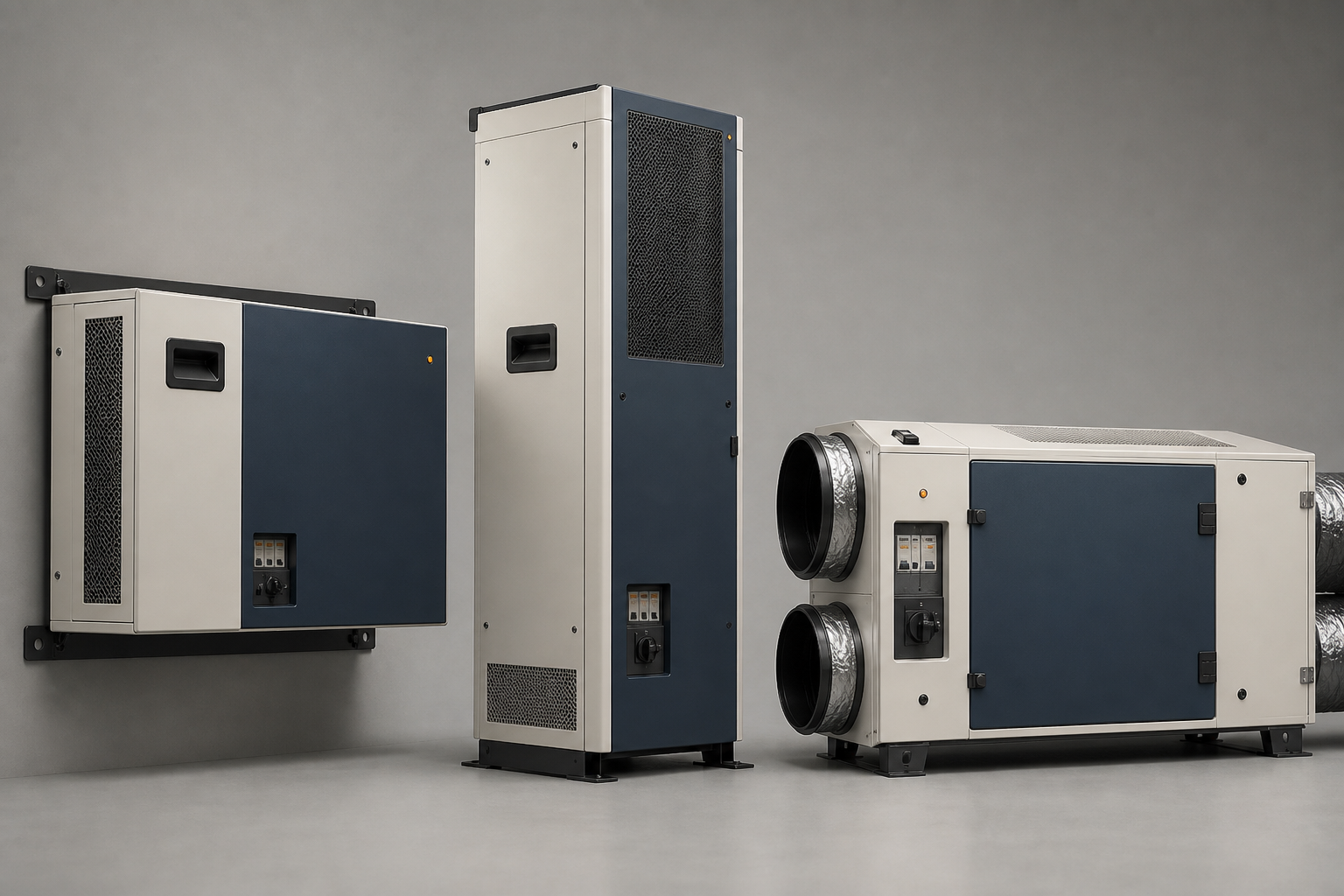
Desirable first. Inspectable immediately after.
A household should see an appliance it can live with. An installer should see the rails, disconnect, airflow, access and isolation before reading a caption.
These are not three skins over one box. The wall unit protects floor area. The tower buys acoustic surface and a natural vertical air path. The ducted unit gives heat somewhere deliberate to go. None has earned the right to become hardware yet.
- 01Heat is architecture. Intake, exhaust and summer rejection shape the enclosure.
- 02Serviceability stays visible. A field-replaceable compute module needs a human-sized door, fasteners and working clearance.
- 03Warmth is rare. One amber point reports human-facing state; nothing glows for decoration.
- 04No fictional specifications. Dimensions, acoustics and thermal capacity remain validation targets.
The floor stays clear.
A shallow rail-mounted enclosure for garages where every square foot already has a job.
- Placement
- Garage wall
- Service
- Front + side
- Heat path
- Room air
- Hard question
- Summer rejection
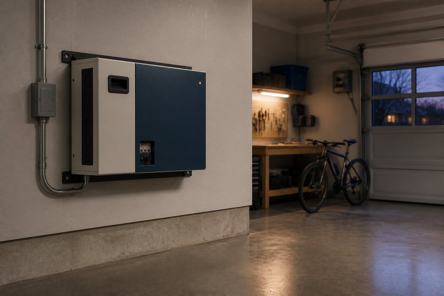
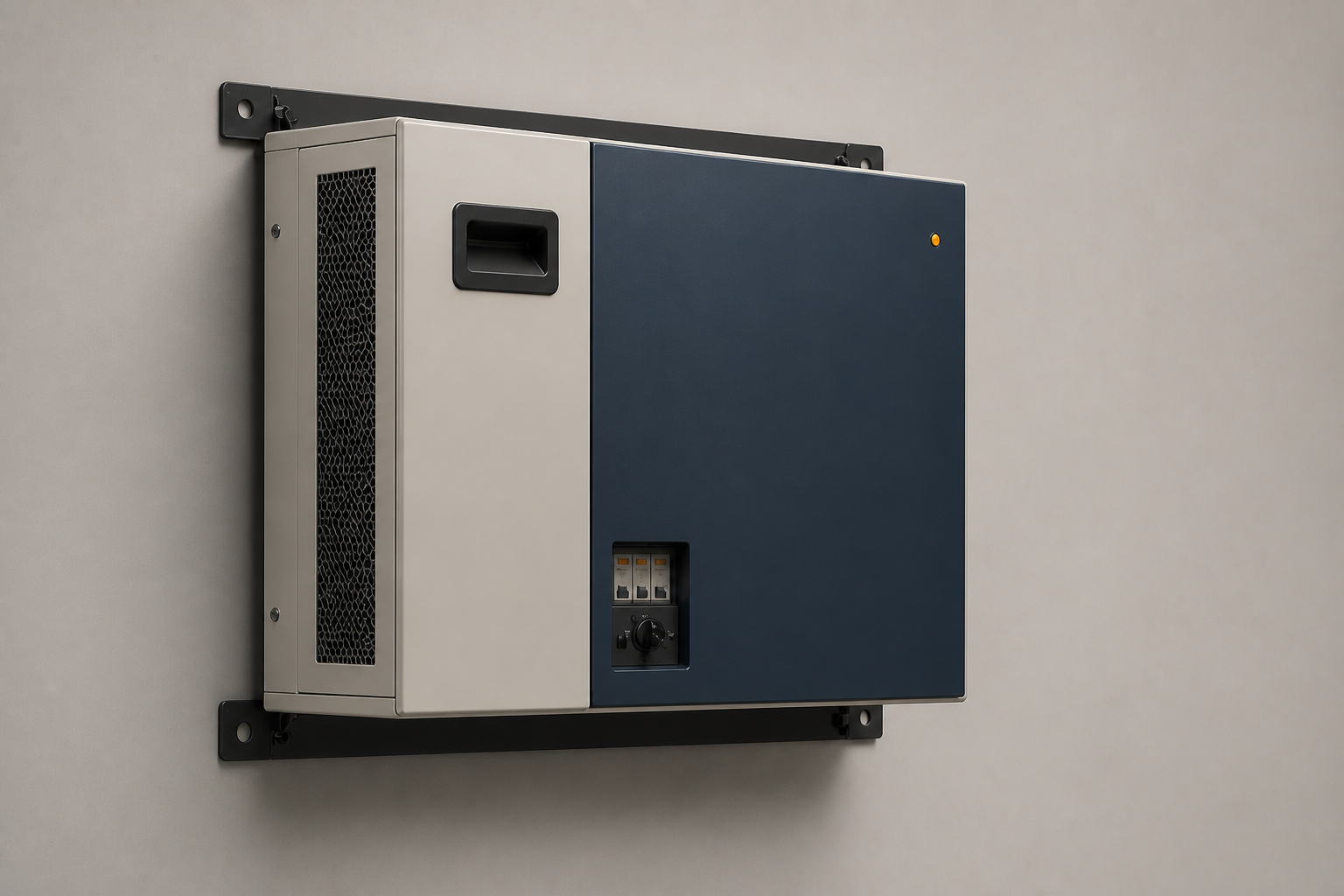
- 01Side intake
Filter access without removing the compute door. - 02Service door
Full-width replaceable module access. - 03Isolation
Local disconnect and metering remain visible. - 04Structural rail
Load transfers to framing, not finish material.
What W1 must prove
W1 only works if a shallow acoustic path can reject sustained heat without turning a garage wall into a loudspeaker.
- Structure-borne vibration at the mounting rail
- Service access with a parked vehicle nearby
- Filter loading in a dusty garage
- A credible exterior-rejection kit for warm weather
Let the heat rise.
A narrow floor unit that spends height on slower air, larger acoustic surfaces and straightforward replacement access.
- Placement
- Basement / garage
- Service
- Front + side
- Heat path
- Bottom to top
- Hard question
- Acoustics
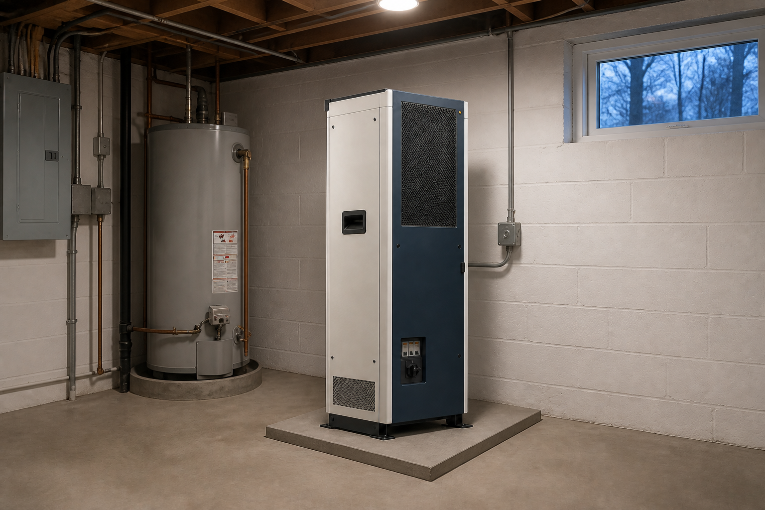
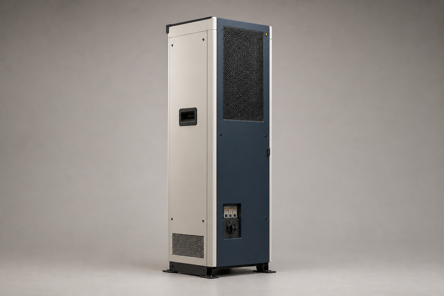
- 01Acoustic exhaust
Large area targets lower air velocity. - 02Lift point
Recessed grip for controlled field handling. - 03Low intake
Filter and plenum remain serviceable. - 04Isolated plinth
Anchoring without hard-coupling the cabinet.
What T1 must prove
T1 trades wall loading for a small footprint and a longer acoustic path. The tower has to earn that floor space with meaningfully quieter operation.
- Tip and seismic stability
- Fan tone and low-frequency vibration through the floor
- Safe hot-air stratification near joists
- Top-plenum options for summer exhaust
Give the heat a destination.
A mechanical-room unit that treats recovered heat and summer rejection as primary interfaces, not accessories.
- Placement
- Mechanical room
- Service
- Full front door
- Heat path
- Ducted / bypass
- Hard question
- HVAC integration
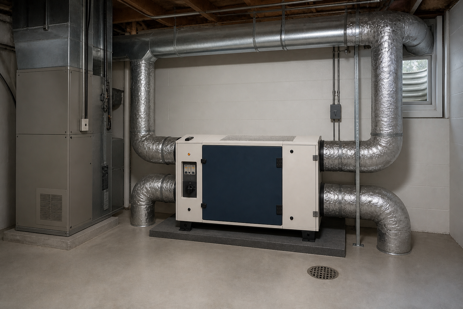
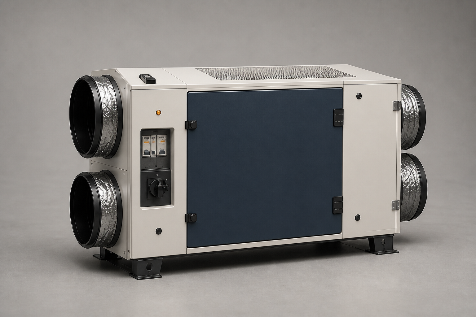
- 01Dual air paths
Recovery and bypass remain separate. - 02Service door
Compute and filter modules leave forward. - 03Local isolation
Meter and disconnect live outside the door. - 04Vibration feet
Cabinet and duct supports remain decoupled.
What D1 must prove
D1 offers the clearest thermal architecture and the hardest installation. It succeeds only if integration is repeatable across homes that were never designed for it.
- Condensation, filtration and pressure balance
- Fail-safe bypass when the home system is off
- Fire and smoke-control boundaries
- HVAC commissioning time and cost
No universal enclosure.
Each study protects a different household constraint. The field pilot should discover which constraint is actually scarce.
| Study | Protects | Heat integration | Installation | Primary unknown |
|---|---|---|---|---|
| W1 / Wall | Floor area | Low without an add-on | Structural rail + dedicated circuit | Noise and summer heat |
| T1 / Tower | Acoustic area | Medium with a top plenum | Pad + anchoring + dedicated circuit | Footprint value and stability |
| D1 / Duct | Thermal control | Highest potential | Electrical + HVAC commissioning | Repeatability across homes |
Appearance is the first prototype, not the last.
The right enclosure will be chosen by measured heat, sound, service time and utility constraints — not by the render people like most.
These studies make the questions physical enough to test. They do not answer them.
- 01Instrument an off-the-shelf compute rig for heat, power and production throughput.
- 02Build acoustic and airflow bucks before designing cosmetic shells.
- 03Review service clearances with electricians, HVAC crews and utility engineers.
- 04Take one installation path through permitting, insurance and inspection.
- 05Only then freeze dimensions and industrial design.